Agile Live Rendering Engine command documentation
This page describes all the commands available in the Agile Live Rendering Engine.
Command protocol
All commands to the Agile Live Rendering Engine is sent as human readable strings and are listed below. The Rendering Engine expect no line termination, meaning that you do not need to append any type of new line (\n) characters, or string termination (\0) characters.
Video commands
Background
The data path of the video mixer in the Rendering Engine looks as follows:
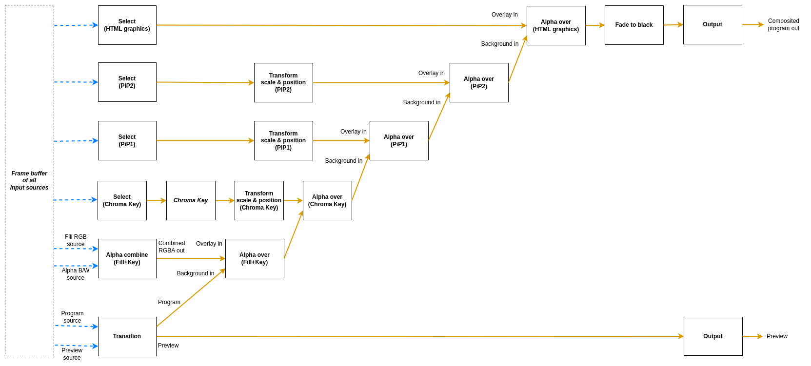
There are eight different node types used in this mixer.
- The
Transitionnode is used to pick which input slots to use for the program and preview output. The node also supports making transitions between the program and preview. - The
Selectnode simply forwards one of the available sources to its output. - The
Transformnode takes one input stream and transforms it (scaling and translating) to one output stream. - The
Alpha combinenode is used to pick two input slots (or the same input slot) to copy the color from one input and combine it with some information from the other input to form the alpha. The color will just be copied from the color input frame, but there are several modes that can be used to produce the alpha channel in the output frame in different ways. This is known as “key & fill” in broadcasting. - The
Alpha overnode is used to perform an “Alpha Over” operation, that is to put the overlay video stream on top of the background video stream, and let the background be seen through the overlay depending on the alpha of the overlay. The node also features fading the graphics in and out by multiplying the alpha channel by a constant factor. - The
Chroma Keynode takes one input stream, and by setting appropriate parameters for the keying, it will remove areas with the key color from the incoming video stream both affecting the alpha and color channels - The
Fade to blacknode takes one input stream, which it can fade to or from black gradually, and then outputs that stream. - The
Outputnode has one input stream and will output that stream out from the video mixer, back to the Rendering Engine
There are six different flows into this mixer. There is the one starting with the Transition node, which represents the main
program that is being produced. Overlaying on top of that is one key+fill graphics overlay (starting with an Alpha Combine node which can combine two video inputs with key form one and fill from another, or both from the same source),
then there is a chroma key overlay, which can be used to add green screen effects (Starting with a Select node), then there are two instances of picture-in-picture flows (also starting with select nodes) and on top of that another graphics overlay, called HTML graphics in the illustration, but which can be used with any source where the key and fill comes from the same source.
The overlay flows are inserted into the main program using Alpha over nodes.
Each video command in the Rendering Engine command protocol targets one of these nodes.
Transitions
The main flow of the video mixer can be controlled with the following commands:
transition cut <input_slot>- Cut (hot punch) the program output to the given input slot. This won’t affect the preview output.transition preview <input_slot>- Preview the given input slot. This won’t affect the program output.transition cut- Cut between the current program and preview outputs, effectively swapping their place.transition panic <input_slot>- Cut (hot punch) both the preview and program output to the given input slot.
Some transition commands last over a duration of time, for example wipes. These can be performed either automatically or manually. The automatic mode works by the operator first selecting the type of transition, for instance a fade, setting the preview to the input slot to fade to and then trigger the transition at the right time with a set duration for the transition. In manual mode the exact “position” of the transition is set by the control panel. This is used for implementing T-bars, where the T-bar repeatedly sends the current position of the bar. In the manual mode, the transition type is set before the transition begins, just as in the automatic mode. Note that an automatic transition will be overridden in case the transition “position” is manually set, by interrupting the automatic transition and jumping to the manually set position.
transition type <type>- Set the transition type to use for transitions hereafter. Valid modes are:fade- Fade (mix) from one source to the nextwipe_left- Wipe from one source to the next, wipe going from right side of the screen to the leftwipe_right- Wipe from one source to the next, wipe going from left side of the screen to the right
transition auto <duration_ms>- Perform an automatic transition from the current program output to the current preview output, lasting for<duration_ms>milliseconds. The currently set transition type is used.transition factor <factor>- Manually set the position/factor of the transition.<factor>should be between 0.0 and 1.0, where 0.0 is the value before the transition starts and 1.0 is the end of the transition. Note that setting this value to 1.0 will effectively swap place of program and preview output, resetting the transition factor to 0.0 internally. Control panels using this command must take this into consideration to not cause a sudden jump in the transition once the physical control is moved again. Sending this command will interrupt any ongoing automatic transition.
Key and fill
The key and fill graphics flow will be inserted before the picture-in-picture flows, and will therefore be rendered under them. The graphics flow can be controlled with these commands:
alpha_combine color <input_slot>- Set which input slot to copy the color data from in the Alpha combine nodealpha_combine alpha <input_slot>- Set which input slot to use to create the alpha channel of the output frame in the Alpha combine nodealpha_combine mode <mode>- Set which way the alpha channel of the output frame will be produced. Valid modes are:copy-r- Copy the R-channel of the input “alpha frame” and use it as alpha for the outputcopy-g- Copy the G-channel of the input “alpha frame” and use it as alpha for the outputcopy-b- Copy the B-channel of the input “alpha frame” and use it as alpha for the outputcopy-a- Copy the A-channel of the input “alpha frame” and use it as alpha for the outputaverage-rgb- Take the average of the R, G and B channels of the input “alpha frame” and use it as alpha channel for the output
alpha_over factor <factor>- Manually set the transparency multiplier for the Alpha over node. The value<factor>should be a float between 0.0 and 1.0, where 0.0 means that the overlay is completely invisible and 1.0 means that the overlay is fully visible (where it should be visible according to the overlay image’s alpha channel). Default is 0.0.alpha_over fade to <duration_ms>- Start an automatic fade from the current factor to a fully visible overlay over the duration of<duration_ms>milliseconds.alpha_over fade from <duration_ms>- Start an automatic fade from the current factor to a fully invisible overlay over the duration of<duration_ms>milliseconds.
Picture-in-Picture
The two picture-in-picture boxes can be controlled with these commands:
pip1_select cut <input_slot>- Choose which input slot to forward. Changing looks like a cut.pip1_transform scale <factor>- Set the scale of the picture-in-picture box, relative the original size. Parameter factor must be > 0. Default is 1.0.pip1_transform x <position>- Set the X offset of the top left corner of the picture-in-picture box, relative the top left corner of the frame. Position is measured in percent of frame width, where 0.0 is the left side of the frame and 1.0 is the right side of the frame. Values outside of the range 0, 1 are valid. Default is 0.0.pip1_transform y <position>- Set the Y offset of the top left corner of the picture-in-picture box, relative the top left corner of the frame. Position is measured in percent of frame height, where 0.0 is the top of the frame and 1.0 is the bottom of the frame. Values outside of the range 0, 1 are valid. Default is 0.0.pip1_alpha_over factor <factor>- Manually set the transparency multiplier for the picture-in-picture 1 Alpha over node. The value<factor>should be a float between 0.0 and 1.0, where 0.0 means that the picture-in-picture box is completely invisible and 1.0 means that the box is fully visible. Default is 0.0.pip1_alpha_over fade to <duration_ms>- Start an automatic fade from the current factor to a fully visible picture-in-picture box over the duration of<duration_ms>milliseconds.pip1_alpha_over fade from <duration_ms>- Start an automatic fade from the current factor to a fully invisible picture-in-picture box over the duration of<duration_ms>milliseconds.
For the second picture-in-picture flow, replace pip1 with pip2.
Chroma Key
The nodes of the chroma key branch of the graph can be controlled with these commands:
chroma_key_select cut <input_slot>- Choose which input slot to forward. Changing looks like a cut.chroma_key r <value>- Set the red component of the chroma key color. Should be a float between 0.0 and 1.0.chroma_key g <value>- Set the green component of the chroma key color. Should be a float between 0.0 and 1.0.chroma_key b <value>- Set the blue component of the chroma key color. Should be a float between 0.0 and 1.0.chroma_key distance <value>- Set the distance parameter, ranging from 0.0 to 1.0, telling how far from the key color is also considered a part of the key. Larger values will result in more colors being included, 0.0 means only the exact key color is considered.chroma_key falloff <value>- Set the falloff parameter, ranging from 0.0 to 1.0, which makes edges smoother. A lower value means harder edges between the key color and the parts to keep, a higher value means a more smooth falloff between removed and kept parts.chroma_key spill <value>- Set the color spill reduction parameter, ranging from 0.0 to 1.0, which will desaturate the key color in the parts of the image that are left. Useful for hiding green rims around objects in from of a green screen etc. 0.0 means off and a higher value means more colors further away from the chroma key color will be desaturated.chroma_key color_picker <x_factor> <y_factor> <square_size>- Set the chroma key by sampling the pixels covered by the square area of size square_size x square_size. The position x,y is set by<x_factor>* width of video and<y_factor>* height of video.<x_factor>&<y_factor>should be a float between 0.0 and 1.0. The<square_size>should be an integer > 0.0.chroma_key alpha_as_video <value>- Instead of writing an alpha mask, set the alpha value as the RGB value, creating a grayscale image of the mask. Value should be 0.0 or 1.0.chroma_key show_key_color <value>- Draw a 100x100 box in upper left corner with the current chroma key (RGB) value. Value should be 0.0 or 1.chroma_key show_color_picker <value>- Draw a pink border around the area where the color picker will sample a new chroma key. Value should be 0.0 or 1.chroma_key_transform scale <factor>- Set the scale of the chroma key output, relative the original size. Parameter factor must be > 0.0. Default is 1.0.chroma_key_transform x <position>- Set the X offset of the top left corner of the chroma key output, relative the top left corner of the frame. Position is measured in percent of frame width, where 0.0 is the left side of the frame and 1.0 is the right side of the frame. Values outside of the range 0.0, 1.0 are valid. Default is 0.0.chroma_key_transform y <position>- Set the Y offset of the top left corner of the chroma key output, relative the top left corner of the frame. Position is measured in percent of frame height, where 0.0 is the top of the frame and 1.0 is the bottom of the frame. Values outside of the range 0.0, 1.0 are valid. Default is 0.0.chroma_key_alpha_over factor <factor>- Manually set the transparency multiplier for the chroma key Alpha over node. The value<factor>should be a float between 0.0 and 1.0, where 0.0 means that the chroma key output is completely invisible and 1.0 means that the chroma key output is fully visible. Default is 0.0.chroma_key_alpha_over fade to <duration_ms>- Start an automatic fade from the current factor to a fully visible chroma key output over the duration of<duration_ms>milliseconds.chroma_key_alpha_over fade from <duration_ms>- Start an automatic fade from the current factor to a fully invisible chroma key output over the duration of<duration_ms>milliseconds.
Graphics overlay (HTML)
The overlay graphics flow, marked with HTML in the illustration. This will be inserted on top of both the key and fill and picture-in-picture. It can be controlled with these commands:
html_select cut <input_slot>- Choose which input slot to use for the graphics. It must contain both fill and key (such as the HTML graphics), otherwise, no parts of the layer will be transparent. Changing looks like a cut.html_alpha_over factor <factor>- Manually set the transparency multiplier for the graphics overlay Alpha over node. The value<factor>should be a float between 0.0 and 1.0, where 0.0 means that the graphics is completely invisible and 1.0 means that it is fully visible. Default is 0.0.html_alpha_over fade to <duration_ms>- Start an automatic fade from the current factor to a fully visible graphics over the duration of<duration_ms>milliseconds.html_alpha_over fade from <duration_ms>- Start an automatic fade from the current factor to a fully invisible graphics over the duration of<duration_ms>milliseconds.
Fade to black
The fade to black node can be controlled via the following commands:
fade_to_black factor <factor>- Manually set the blackness factor on a scale from 0.0 to 1.0, where 0.0 means not black and 1.0 means fully black output.fade_to_black fade to <duration_ms>- Start an automatic fade to a fully black output over the duration of<duration_ms>milliseconds.fade_to_black fade from <duration_ms>- Start an automatic fade to a fully visible (non-black) output over the duration of<duration_ms>milliseconds.
Audio Router commands
The same audio router is used to route specific audio channels from an input slot of the Rendering Engine to an input channel strip on the audio mixer. By default, it has no audio routes set up. The router can be controlled with the following commands:
audio map <input_slot> <channel> mono <input_strip>- Map the<channel>from input slot<input_slot>as a mono channel into input strip<input_strip>of the audio mixeraudio map <input_slot> <left_channel> stereo <input_strip>- Map the<left_channel>and<left_channel> + 1from input slot<input_slot>as a stereo pair into input strip<input_strip>of the audio mixer ’audio map reset <input_strip>- Remove the current mapping from<input_strip>of the audio mixer.
Audio commands
The audio mixer and audio router have the following data path:
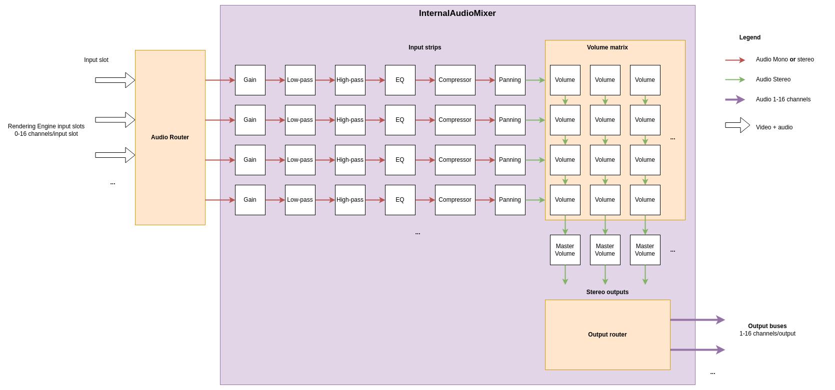
In the example picture above, three sources are connected to the input slots and four mono or stereo audio streams are picked as input to the audio mixer. The audio mixer is completely separate from the video mixer, so switching image in the video mixer will not change the audio mixer in any way. The internal audio mixer can be controlled using the following commands:
To control the pre-gain of each input strip use:
audio gain <input_strip> <level_dB>- Set the pre-gain level of a specific input in dB. Parameter<level>should be a floating point number. Default is 0.0.
To control the low-pass filter of each input strip use:
audio lpf <input_strip> freq <value>- Set the cutoff frequency for the low-pass filter in an input strip.<value>is the frequency in Hz as a floating point number. The frequency range is 20 Hz to 20 kHz. Setting a value of 20 kHz or higher will bypass the filter.audio lpf <input_strip> q <value>- Set the q-value for the low-pass filter in an input strip. The q-value controls the steepness of cutoff curve with a higher value being a steeper slope. The value is a floating point number ranging from 0.4 to 6.0. The default value is 0.7.
To control the high-pass filter of each input strip use:
audio hpf <input_strip> freq <value>- Set the cutoff frequency for the high-pass filter in an input strip.<value>is the frequency in Hz as a floating point number. The frequency range is 20 Hz to 20 kHz. Setting a value of 20 Hz or lower will bypass the filter.audio hpf <input_strip> q <value>- Set the q-value for the high-pass filter in an input strip. The q-value controls the steepness of cutoff curve with a higher value being a steeper slope. The value is a floating point number ranging from 0.4 to 6.0. The default value is 0.7.
To control the parametric equalizer of each input strip use (the equalizer has three bands):
audio eq <input_strip> <band> freq <value>- Set the frequency of a specific band in the parametric equalizer. Here<band>is a zero based index of the band, where 0 is the first band with the lowest frequency.<value>is a floating point number with the frequency in Hzaudio eq <input_strip> <band> gain <value>- Set the gain of a specific band in the parametric equalizer. Here<band>is a zero based index of the band, where 0 is the first band with the lowest frequency.<value>is a floating point number with the gain in dB.audio eq <input_strip> <band> q <value>- Set the q-value of a specific band in the parametric equalizer to shape the falloff of the band. Here<band>is a zero based index of the band, where 0 is the first band with the lowest frequency.<value>is a floating point number with the q-value where a higher value means a more pointy curve. Default value is 0.7.audio eq <input_strip> <band> type <type>- Set the type of falloff to use for a specific band in the parametric equalizer. Here<band>is a zero based index of the band, where 0 is the first band with the lowest frequency.<type>is either oflow,bandorhigh, where low and high is a low and high shelf filter and band is a band pass filter. By default, the first band is low shelf, the last band is high shelf and any bands inbetween are band pass.
To control the panning of each input strip use:
audio pan <input_strip> <factor>- Pan the mono or stereo input of an input strip to the left or right. The range of<factor>is between -1.0 and +1.0, where 0.0 means center (no panning), negative values means more to the left and positive value more to the right. Values outside this range will be clamped. A value of +/- 1.0 means that there will only be audio in the left/right channel.
To control the dynamic range compressor of each input strip use:
audio comp <input_strip> threshold <value>- Set the threshold for activation of the compressor. The threshold is a negative dB value ranging from -30 dB to 0 dB. The volume of audio which is above the threshold value will be reduced (compressed). The default value is 0 dB, i.e. only compression if the audio signal is overloaded.audio comp <input_strip> ratio <value>- Set the compression ratio for audio exceeding the loudness threshold. The value is the numerator in the compression ratio<value>:1. For instance, if the value is set to 4, the compression ratio is 4:1 and volume overshoot above the threshold will be scaled down to 25 %. The ratio numerator is a floating point number in the range from 1.0 to 24.0, with 4.0 as the default value.audio comp <input_strip> knee <value>- Set the width of the soft knee in decibels. Instead of simply turning the compression completely on or off at the threshold, the knee defines a volume range in which the compression ratio follows a curve, the “knee”. The knee is a floating point number between 0 dB and 30 dB, with a default value of 2.5 dB.audio comp <input_strip> attack <value>- Set the attack time of the compressor in milliseconds. The attack time determines how long it takes to reach the full compression after the threshold has been exceeded. The value is a floating point number in the range from 0.1 ms to 120 ms. The default value is 50 ms.audio comp <input_strip> release <value>- Set the release time of the compressor in milliseconds. The release time determines how long it takes to return to zero compression when the volume is below the compression threshold. The value is a floating point number in the range from 10 ms to 1000 ms. The default value is 200 ms.audio comp <input_strip> gain <value>- Set the make-up gain i decibels. Since the compression filter lowers the volume of louder audio sections it can be desirable to increase the gain after the filtering. The gain value increases the audio volume with the specified number of decibels. The value is a floating point number in the range from 0 dB to 24 dB. The default value is 0 dB.
To control the volume faders and master volume faders use:
audio volume <input_strip> <output> <level>- Set the volume level of a specific input in proportion to its original strength for a given output. Parameter<level>should be a floating point number, where 0.0 means that the input slot is not mixed into the output at all and 1.0 means that the volume of the input slot is kept as is for the output. The signal can also be amplified by using values > 1.0. Default is 0.0.audio mastervolume <output> <level>- Set the master volume level of an output, before the audio is clamped and converted from floating point samples to 16-bit integer samples. This can be used to avoid clipping of the audio when mixing multiple input sources. Parameter<level>is a floating point number where 0.0 means that all audio output is off, 1.0 means that the volume is not changed and any value above 1.0 means that the master volume is amplified. Default is 1.0.
HTML rendering
The Rendering Engine also features a built-in HTML renderer which uses the Chromium web browser engine to render HTML pages. The following commands can be used to create and control the HTML browser instances:
html create <input_slot> <width> <height>- Create a new HTML browser instance with the canvas size ofwidthxheightpixels and output the rendered frames to the given input slothtml close <input_slot>- Close the HTML browser instance on the given input slothtml load <input_slot> <url>- Load a new URL in the HTML browser on the given input slothtml execute <input_slot> <java script>- Execute JavaScript in the HTML browser on the given input slot. The JavaScript snippet might span over multiple lines and may contain spaces.
Media player
The Rendering Engine can create media player instances to play video and audio files from the hard drive of the machine running the Rendering Engine. It is up to the user of the API to ensure the files are uploaded
to the machines running the Rendering Engine(s) before trying to run them. The media players use the FFmpeg library to demux and decode the media files, so most files supported by FFmpeg should work.
The media players each have three state parameters: start, duration and looping, to mark a section of the video to loop, or a last frame to stop at in case looping is set to false.
The following commands can be used to create and control the media player instances:
media create <input_slot> <filename>- Create a new media player instance with the given media file and output the rendered frames to the given input slot.media load <input_slot> <filename>- Load another file into an existing media player on the given input slot. This will reset the start, duration and looping parameters of that media player.media close <input_slot>- Close the media player instance on the given input slotmedia play <input_slot>- Start/resume playing the currently loaded media file in the media player on the given input slotmedia pause <input_slot>- Pause the media player on the given input slotmedia seek <input_slot> <time_ms>- Seek the media player on the given input slot to a time pointtime_msmilliseconds from the start of the media file and pause the playback at the first frame. Usemedia play <input_slot>to resume the playbackmedia set_start <input_slot> <start_time_ms>- Set the start time of the looping section of the media player on the given input slot to a time pointstart_time_msmilliseconds from the start of the media file. It will still be possible to seek before this time point and play the video from there.media set_duration <input_slot> <duration_ms>- Set the duration of the playing/looping section of the media player on the given input slot toduration_msmilliseconds from thestart_time_msof the media file. The duration will be clamped in case it spans past the end of the media file. A running media player will either stop at this point, or loop the video depending on the state of the looping parametermedia set_looping <input_slot> <true/false>- Set if the media should loop from the start time when the media player on the given input slot hits either the end of the looping section defined by the start time and duration, or the end of the media file. If set to false, the media player will stop at the end of the section or at the end of the file instead of looping it from the start point.