Agile Live Rendering Engine configuration documentation
This page describes how to configure the Rendering Engine. This topic is closely related to this page on the control command protocol for the video and audio mixers.
Rendering Engine components
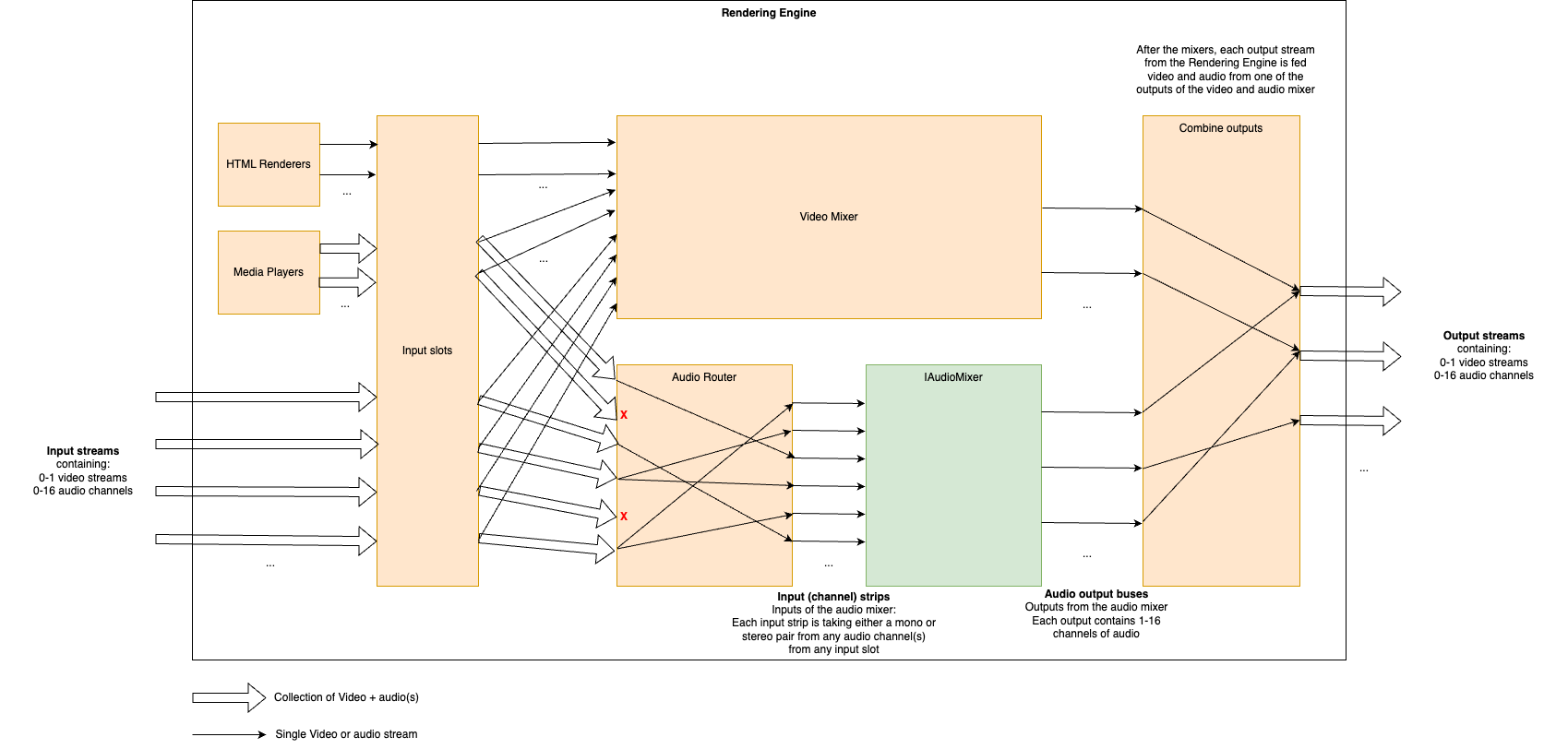
The Rendering Engine is an application that uses the Production Pipeline library in the base platform for transport, and adds to that media file playback, HTML rendering, a full video mixer and an audio router and audio mixer. The figure below shows a schematic of the different components and an example of how streams may transition through it.
HTML Renderers
Multiple HTML renderers can be instantiated in runtime by control panels, and in each an HTML page can be opened. Each HTML renderer produces a video stream, but no audio.
Media Players
Multiple media players can be instantiated in runtime by control panels, and in each a media file can be opened. Each media player produces a stream containing a video stream and all audio streams from the file.
Video Mixer
The Video mixer receives all video inputs into the system, i.e. streams from ingests, from HTML renderers and from media players. It outputs one or more named video output streams. The internal structure of the video mixer is defined at startup (as decribed in detail below), and controlling the video mixer is done in runtime by control panels.
Audio Router
The audio router receives all audio streams into the system, i.e. streams from ingests and from media players. It outputs a set of streams that are either mono or a stereo pair, to the audio mixer. The mappings from input streams to output streams in the router is configured in runtime by control panels.
Audio Mixer
Note
The audio mixer can be either our internal audio mixer or an integration towards an external third party audio mixer. The rest of the documentation here is valid for the internal audio mixer.The audio mixer takes a number of mono or stereo pair streams as inputs that we call input strips. It outputs a number of named output streams in stereo. The outputs of the audio mixer are defined at startup, and the audio mixer is controlled in runtime by control panels.
Combine outputs
The combination of video and audio outputs into full output streams from the rendering engine is configured at startup.
Configuring the Rendering Engine
Some aspects of the rendering engine can be configured statically at startup through the use of a configuration file in JSON format. Specifically, the video mixer node graph, the audio mixer outputs and the combination of video and audio outputs can be configured. As an example, here is such a JSON configuration file that we will refer to throughout this guide:
{
  "version": "1.0",
  "video": {
    "nodes": {
      "transition": {
        "type": "transition"
      },
      "chroma_key_select": {
        "type": "select"
      },
      "chroma_key": {
        "type": "chroma_key"
      },
      "chroma_key_alpha_over": {
        "type": "alpha_over"
      },
      "fade_to_black": {
        "type": "fade_to_black"
      },
      "program": {
        "type": "output"
      },
      "chroma_key_preview": {
        "type": "output"
      },
      "preview": {
        "type": "output"
      }
    },
    "links": [
      {
        "from_node": "transition",
        "from_socket": 0,
        "to_node": "chroma_key_alpha_over",
        "to_socket": 1
      },
      {
        "from_node": "transition",
        "from_socket": 1,
        "to_node": "preview",
        "to_socket": 0
      },
      {
        "from_node": "chroma_key_select",
        "from_socket": 0,
        "to_node": "chroma_key",
        "to_socket": 0
      },
      {
        "from_node": "chroma_key",
        "from_socket": 0,
        "to_node": "chroma_key_alpha_over",
        "to_socket": 0
      },
      {
        "from_node": "chroma_key_alpha_over",
        "from_socket": 0,
        "to_node": "fade_to_black",
        "to_socket": 0
      },
      {
        "from_node": "fade_to_black",
        "from_socket": 0,
        "to_node": "program",
        "to_socket": 0
      },
      {
        "from_node": "chroma_key",
        "from_socket": 0,
        "to_node": "chroma_key_preview",
        "to_socket": 0
      }
    ]
  },
  "audio": {
    "outputs": [
      {
        "name": "main",
        "channels": 2
      },
      {
        "name": "aux1",
        "channels": 2,
        "follows": "main"
      },
      {
        "name": "aux2",
        "channels": 2
      }
    ]
  },
  "output_mapping": [
    {
      "name": "program",
      "video_output": "program",
      "audio_output": "main",
      "feedback_input_slot": 1001,
      "stream": true
    },
    {
      "name": "preview",
      "video_output": "preview",
      "audio_output": "",
      "feedback_input_slot": 1002,
      "stream": false
    },
    {
      "name": "aux1",
      "video_output": "program",
      "audio_output": "aux1",
      "feedback_input_slot": 0,
      "stream": true
    },
    {
      "name": "chroma_key_preview",
      "video_output": "chroma_key_preview",
      "audio_output": "aux2",
      "feedback_input_slot": 100,
      "stream": true
    }
  ]
}
Video Mixer node graph
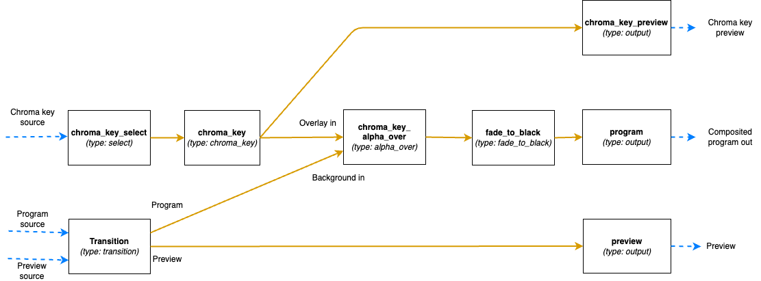
The video mixer is defined as a tree graph of nodes that work together in sequence to produce one or several video outputs. Each node performs a specific action, and has zero or more input sockets and zero or more output sockets. Links connect output sockets on one node to input sockets on other nodes. Each node is named and the name is used to control the node in runtime. The node tree configuration is specified in the video section of the JSON file, which contains two parts: the list of nodes and the list of links connecting the nodes.
The following is a graphical representation of the video mixer node graph configuration in the JSON example file above, with two input nodes, three processing nodes and three output nodes, and links in between:
Video nodes block
The nodes object of the video block is a JSON object where the names/keys in the object is the unique name of the
node. The name is used to refer to the node when operating the mixer later on, so names that are easy to
understand what they are supposed to be used for in the production is recommended.
The name can only contain lower case letters, digits, _ and -. Space or other special characters are not allowed.
Each node is an JSON object with parameters defining the node properties.
Here the parameter type defines which type of node it is.
The supported types are listed below. They can be divided into three groups depending on if they provide input to the
graph, output from the graph or is a processing node, placed in the middle of the graph.
Input nodes
The input nodes take their input from the input slots of the Rendering Engine, which contains the latest frame for all connected sources (this includes connected cameras, HTML graphics, media players etc.) The nodes in this group does not have any input sockets, as they take the input frames from the input slots of the Rendering Engine. Which slot to take the frames from is dynamically controlled during runtime.
Alpha combine node (alpha_combine)
Input sockets: 0 (Sources are taken from the input slots of the mixer)
Output sockets: 1
The alpha combine node takes two inputs and combines the color from one of them with the alpha from the other one. The
node features multiple modes that can be set during runtime to either pick the alpha channel of the second video input,
or to take any of the other R, G and B channels, or to average the RGB channels and use as alpha for the output.
This node is useful in case videos with alpha is provided from SDI sources, where the alpha must be sent as a separate
video feed and then combined with the fill/color source in the mixer.
Select node (select)
Input sockets: 0 (Source is taken from the input slots of the mixer)
Output sockets: 1
The select node simply selects an input slot from the Rendering Engine and forwards that video stream.
Which input slot to forward is set during runtime.
The node is a variant of the transition node, but does not support the transitions supported by the transition node.
Transition node (transition)
Input sockets: 0 (Sources are taken from the input slots of the mixer)
Output sockets: 2 (One with the program output and one with the preview output)
The transition node takes two video streams from the Rendering Engine’s input slots, one to use as the program and one
as the preview output stream.
These are output through the two output sockets.
During runtime this node can be used to make transitions such as wipes and fades between the selected program and
preview.
Output nodes
This group only contains a single node, used to mark a point where processed video can exit the graph and be used in output mappings.
Output node (output)
Input sockets: 1
Output sockets: 0 (Output is sent out of the video mixer)
The output node marks an output point in the video mixer’s graph, where the video stream can be used by the output
mapping to be included in the Rendering Engine’s Output streams, or as streams to view in the multi-viewer.
The node takes a single input and makes it possible to use that video feed outside the video mixer.
Output nodes can be used both to output the program and preview feeds of a video mixer, but also to mark auxiliary
outputs, as in the example above, where chroma_key_preview is output to be included in the graph to be able to view
the result of the chroma keying, without the effect being keyed on to the program output.
Processing nodes
The processing nodes take their input from another node’s output and outputs a result that is sent to another node’s input. They are therefore placed in the middle of the graph, after nodes from the input group and before output nodes.
Alpha over node (alpha_over)
Input sockets: 2 (Index 0 for overlay video and index 1 for background video)
Output sockets: 1
The alpha over node composites the overlay video input on top of the background video input. The alpha of the overlay
video input is taken into consideration. During runtime, this node can be controlled to show or not to show the overlay,
and to fade the overlay in or out. This node is useful to composite things such as graphics or chroma keyed video onto a
background video.
Chroma key node (chroma_key)
Input sockets: 1
Output sockets: 1
The chroma key node takes an input video stream and performs chroma keying on it based on parameters set during runtime.
The video output will have the alpha channel (and in some cases also the color channels) altered. The result of this
node can then be composited on top of a background using an Alpha over node.
Fade to black node (fade_to_black)
Input sockets: 1
Output sockets: 1
The fade to black node takes a single input video stream and can fade that video stream to and from black.
This node is normally used as the last node before the main program output node, to be able to fade to and from black at
the beginning and end of the broadcast.
Transform node (transform)
Input sockets: 1
Output sockets: 1
The transform node takes an input video stream and transform the result inside the visible canvas. This node can be
configured during runtime to scale and move the input video. This node is useful for picture-in-picture effects, or to
move a chroma key node output to the lower corner of the frame.
Video delay node (video_delay)
Input sockets: 1
Output sockets: 1
The video delay node is used to delay the video by a given number of frames. The number of frames to delay is controlled
during runtime. This node is useful whenever the need for dynamically delay a video stream arises, for example in
case an external audio mixer is used, which comes with a delay of some frames.
Video links block
The links array in the video block is a list of links between video nodes. The video frames are fed in one direction
from node to node via these links.
An input socket on a node can only have one connected link.
The output sockets on a node can have multiple connected links.
Each block contains the following keys:
from_node- The name of the node in thenodesobject, from which the link is receiving frames fromfrom_socket- The index of the output socket in the node from which this link originatesto_node- The name of the node in thenodesobject, to which the link is sending frames toto_socket- The index of the input socket in the node to which this link connects
Some examples
The simplest video mixer node graph imaginable would be a select node feeding an output node. This mixer would only be able to select one of the inputs and output it unaltered, like a video router would do: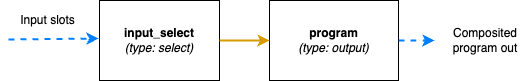
The JSON file section for this is:
"video": {
  "nodes": {
    "input_select": {
      "type": "select"
    },
    "program": {
      "type": "output"
    }
  },
  "links": [
    {
      "from_node": "input_select",
      "from_socket": 0,
      "to_node": "program",
      "to_socket": 0
    }
  ]
}
A slightly more advanced node graph would be to use a transition node and two outputs, one for the program out and one for the preview: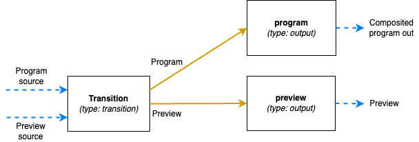
The JSON file section for this is:
"video": {
  "nodes": {
    "transition": {
      "type": "transition"
    },
    "program": {
      "type": "output"
    },
    "preview": {
      "type": "output"
    }
  },
  "links": [
      {
        "from_node": "transition",
        "from_socket": 0,
        "to_node": "program",
        "to_socket": 0
      },
      {
        "from_node": "transition",
        "from_socket": 1,
        "to_node": "preview",
        "to_socket": 0
      },
  ]
}
Audio outputs
The audio block of the configuration file defines the properties of the audio mixer.
The JSON object contains a list called outputs which lists the outputs of the audio mixer and the configuration of
each output.
Each output has these parameters:
name- The unique name of this audio output, used to refer to if from theoutput_mappingblockchannels- The number of audio channels of this outputfollows- (Optional parameter) Used to identify the audio output this output is a post fader aux output for. If the output does not have this parameter set, it is considered a main output
The follows parameter is used to set the output in “post fader aux send” mode.
This is used to create extra aux outputs from the audio mixer which are used for mix minus, i.e. where you want the
program output, but with some specific audio source(s) removed.
When follows is set, the volume of that output will follow the volume of the main bus and scale that volume.
If the volume fader of the aux bus is up, it will send the same volume of audio of that strip as the main bus does.
So when the main bus volume is turned down, the same thing will happen automatically in the aux bus.
If an aux bus’ fader is down on the other hand, that strip will not contribute to the aux bus at all.
The aux bus volume faders can therefore be used to remove audio (or scale the volume up or down), but cannot be used to
add more audio strips compared to the main bus it is following.
The input routing and configuration of the strips is made via the control command API.
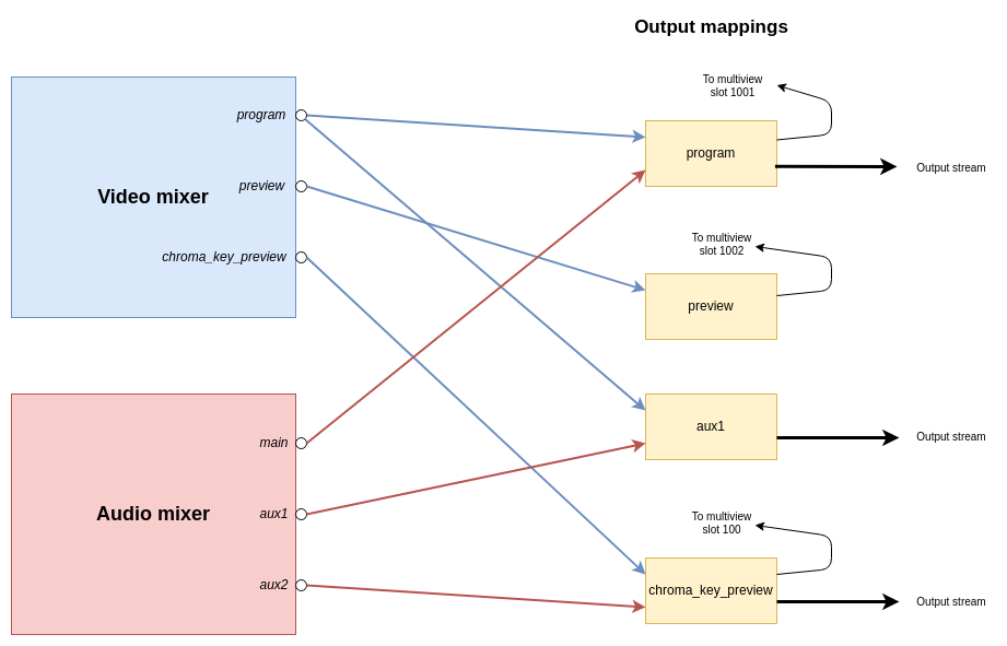
Combine outputs
The output_mapping block is used to define outputs of the entire Rendering Engine, by combining outputs from the video
and audio mixers and configuring where those should be sent.
The output mapping is an array of output mappings. Each mapping has the following parameters:
name- The unique name of the output mapping. This will be displayed in the REST API both for sources being streamed and sources with feedback streams that can be included in the multi-viewvideo_output- The name of the video mixer node of typeoutputto get the video stream from. Leave empty, or omit the key to create an audio-only outputaudio_output- The name of the audio output to get the audio stream from. Leave empty, or omit the key to create a video-only outputfeedback_input_slot- The input slot to use to feed this output back to the multi-view. The REST API may then refer to this input slot to include this output in a multi-view view. Value must be >= 100 as input slots up to 99 are reserved for “regular” sources. Use 0 to disable feedback of this stream.stream- Boolean value to tell if the output should be streamable and visible as an output in the REST API. If set to false the output will not turn up as anPipeline Outputin the REST API.
The following is a graphical visualisation of the output mappings in the JSON example configuration file above: